Guides to custom cable
Designing a high-performance custom medical cable requires a rigorous alignment between theoretical electrical properties and harsh clinical execution environments. As an ISO 13485 certified manufacturer, Shen Zhen Yong Qiang Fu Industry Co.,Ltd. (operating globally as Conectmed) provides this comprehensive engineering design guide to help medical device R&D leaders calculate impedance matching, select biocompatible jacket materials, and specify shielding matrices. Use the practical data tables below to finalize your raw master-spool architecture.
Definition
1. ATTENUATION – Attenuation is loss of power or signal expressed in decibels; it is commonly written and spoken of as dB/100 ft. at a specific frequency. An example is RG 8A/U which has a loss of 5.5 dB/100 ft. at 400 MHz.
2. FREQUENCY – Frequency is the term designating the number of reverses or cycles in the flow of alternating current (AC) in one second. For example, the frequency of AC commonly used in the U.S. is 60 hertz and is usually shown as 60 Hz. Broadcast stations operate at frequencies of thousands of cycles per second and their frequencies are called kilohertz (kHz). Your AM radio dial represents frequencies in kilohertz (kHz). High frequencies are in millions of cycles per second and are called megahertz (MHz). TV is broadcast in the MHz range.
3. IMPEDANCE – Impedance is a term expressing the ratio of voltage to current in a cable of infinite length. In the case of coaxial cables, impedance is expressed in terms of “ohms impedance”.The coaxial cables generally fall into three main classes; 50 ohms, 75 ohms, and 95 ohms.
An example of each class is:
RG 11A/U 75 ohms impedance
RG 22B/U 95 ohms impedance
4. CAPACITANCE (CAPACITY) – Capacitance or capacity is the property of a system of conductors and dielectrics which permits the storage of electricity when a potential or voltage difference exists between the two conductors. A capacity value is expressed in farads.When we deal with coaxial cable, the capacity ranges we have are very small and are expressed in picofarads (pF)
Capacity is the major factor governing impedance. Examples of cables with typical impedances have capacity as follows:
|
RG or M17 |
Cable Impedance (ohms) |
Dielectric Type |
Capacitance (pF/ft) |
| RG 8A/U |
50 |
PE |
29.5 |
|
RG 231A/U |
50 |
Foam PE |
25.0 |
|
RG 188A/U |
50 |
Solid TFE |
29.0 |
|
M17/6 |
75 |
PE |
20.6 |
|
RG 306A/U |
75 |
FoamPE |
16.5 |
|
RG 140 |
75 |
Solid TFE |
21.0 |
|
M17/90 |
93 |
Air space PE |
13.5 |
|
M17/56 |
95 |
PE |
17.0 |
|
M17/95 |
95 |
Solid TFE |
15.4 |
|
RG 24A/U |
125 |
PE |
12.0 |
|
RG 114A/U |
185 |
Air space PE |
6.5 |
5. VELOCITY OF PROPAGATION – Velocity of propagation, commonly called velocity, is the ratio of the speed of the flow of an electric current in an insulated cable to the speed of light. All insulated cables have this ratio and it is expressed in a percent- age. In the case of coaxial cables with polyethylene dielectric, this ratio is in the range of 65% – 66%.
In selecting coaxial cable, we must carefully consider not only design criteria, but use and application. Selection of materials in relation to overall design considerations is tabulated in folowing tables
INNER CONDUCTORS
| INNER CONDUCTORS | ||||||
| SOFT BARE COPPER | TINNED SOFT COPPER | SILVER – PLATED COPPER | NICKEL – PLATED COPPER | TINNED – CADIMUM BRONZE | COPPER WELD® | |
| Maximum operating temperature °C | 200 | 150 | 200 | 250 | 150 | 200 |
| Resistivity at 20°C,ohms – circular mil / ft. | 10.371 | 11.133 | 10.371 | 12.5 | 11.92 | 25.928 |
| Average tensile strength psi (1,000) | 37 | 37 | 37.5 | 37.5 | 45 | 130 |
| Flexibility | excellent | excellent | excellent | excellent | good | good |
| Remarks | most popular – for extra flexibility use stranded | for added resistance to oxidation and easy solderability, best for low frequency application | elevated temperature usein aircraft, missile, and electronics, easy solderability | extra high temperature use | high tensilestrength with flexibility | extra high tensile strength |
Table1-Inner Conductors
| INNER CONDUCTORS | |||||
| SOFT BARE COPPER | TINNED SOFT COPPER | SILVER – PLATED COPPER | ALUMINUM TUBE | COPPER TUBE | |
| Maximum operating temperature °C | 200 | 150 | 200 | – | – |
| Flexibility | excellent | excellent | excellent | poor | poor |
| Remarks | most popular in braid, minimum .004″ to .010″, add second shield to improve flexibility | most popular in braid, minimum .004″ to .010″, add second shield to improve flexibility, better for low frequency | most popular in braid, minimum .004″ to .010″, add second shield to improve flexibility, for high temperature | for high tensile and crushing loads and lower attenuation | for high tensile strength and crushing loads |
Table2-Outer Jackets
| Primary Dielectrics | |||||
| POLYETHYLENE (PE) | FOAMED POLYETHYLENE (PE) | Fluorinated Ethylene Propylene (FEP) | Poly Tetrafluoroethylene (PTFE) | BUTYL RUBBER | |
| Maximum operating temperature °C | -65 to 80 | -65 to 80 | -65 to 200 | -65 to 260 | -40 to 80 |
| Average tensile strength psi (1,000) | 1.9 | 2.2 | 3.6 | 2.7 | 1.1 |
| Flexibility | good | good | excellent | good | excellent |
| Cut-thru resistance | good | poor | good | fair | excellent |
| Water Resistance | excellent | poor | excellent | excellent | good |
| Resistance to organic solvents | poor | poor | excellent | excellent | good |
| Resistance to acids and alkalies | excellent | excellent | excellent | excellent | good |
| Remarks | for use under 80°C maximum | for use under 80°C maximum | for high temperature use to 200°C | for high temperature use to 260°C | for pulse cables and extreme flexibility |
Table 3 - Primary Dielectrics
| JACKETS | ||||||
| POLYETHYLENE | Tetrafluoroe- thylene (TFE) |
Fluorinated Ethylene Propylene (FEP) |
PVC | NEOPRENE® | GLASS BRAID | |
| Maximum operating temperature °C |
80 | 260 | 200 | 105 | 90 | 260 |
| Average tensile strength psi (1,000) |
1.9 | 3.5 | 2.7 | 2.5 | 3.2 | – |
| Flexibility | good | good | good | good | excellent | excellent |
| Resistance to organic solvents |
poor | excellent | excellent | poor | good | excellent |
| Resistance to acids and alkalies |
excellent | excellent | excellent | fair | good | excellent |
| Abrasion resistance | good | excellent | excellent | good | excellent | poor |
| Flame resistance | slow burn | nonflammable | nonflammable | self-extinguishing | self-extinguishing | nonflammable |
| Remarks | for added resistance to weathering |
to mate with high temperature dielectric |
to mate with high temperature dielectric |
most widely used | to mate with Butyl dielectric |
to mate with high temperature dielectric |
Table 4 - Jackets
Defination:
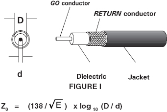
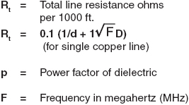
Z0 = Characteristic impedance
E = Dielectric constant (air is 1.0), see Table 5.
D = Inside diameter of the “return” (outer) conductor (conductive metal tube or one or more braids),
see Figure 1.
d = Outside diameter of the “go” (inner)
conductor, see the table on the right.
Dielectric Material | Dielectric | Power |
Air | 1.00 |
|
Polyethylene – cellular foam (PE) | 1.40 – 2.10 | 0.0003 |
Polyethylene – solid (PE) | 2.3 | 0.0003 |
Poly Tetrafluoroethylene | 2.1 | 0.0002 |
Cellular Poly Tetrafluoroethylene | 1.4 | 0.0002 |
Fluorinated Ethylene Propylene | 2.1 | 0.0007 |
Cellular Fluorinated Ethylene | 1.5 | 0.0007 |
Butyl rubber | 3.1 | – |
Silicone rubber | 2.08 – 3.50 | 0.007 – 0.01 |
💡 Shen Zhen Yong Qiang Fu Industry Co.,Ltd. Material Selection Cheat-Sheet for Medical Device R&D:
When matching your dynamic hardware blueprint with the dielectric properties listed above, our engineering team recommends the following clinical frameworks:
* For High-Field MRI RF Coils: Implement Silver-Plated Copper conductors matching with Poly Tetrafluoroethylene (PTFE) or FEP dielectrics (Table 3) to enforce a rigid 50 Ohm characteristic impedance under intensive radiofrequency loads.
* For Surgical Endoscopes & Dynamic Catheters: Specify micro-stranded Tinned Soft Copper braids combined with highly flexible, glossy Medical-Grade TPU jackets to secure absolute chemical wipe resistance and sleek articulation control.
* For Patient-Contact ECG/EEG Leads: Utilize low-noise conductive layer matrices paired with flexible Silicone Rubber jackets to completely eliminate triboelectric noise artifacts during patient movement.
Table 5 - Dielectric Properties
Another important key to the selection of coaxial cable is the required attenuation. The formula for theoretical calculation of attenuation (A) is the attenuation due to conductors plus attenuation due to the dielectric:
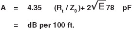
As can readily be seen, attenuation would increase as the frequency increases. In a perfect cable, the pattern of increasing attenuation would be exact and regular. However, on the practical side, this is difficult to achieve and for that reason, tolerances are specified. The military RG specifications spell out in detail the tolerances permitted on various electrical characteristics. Perfect design is based first on the ability to obtain theoretically perfect cable. As with all manufacturing, this is not too practical.
Therefore, the physical tolerances to which cable can be manufactured should be considered as much a part of design as the empirical formulas. These tolerances vary from cable to cable, dependent upon the physical size of the cable and the dielectric material used in its manufacture. Since the manufacture of coaxial cable is a “continuous” type manufacturing process, rather than a “batch” type, there are variations encountered. To ensure that there is no place in the cable which might cause a high attenuation, the cable can be “swept” at various frequencies, particularly those frequencies at or near the expected use of the cable.
If we examine the basic Z0 formula, it becomes quite evident that a difference in the D of only a few thousandths of an inch would significantly affect the impedance and in the 50 ohms group of miniature cables, tolerances become even more important. Even after perfect design, there still remains the practical installation and use to which the cable will be subjected. The power rating, as well as other characteristics, will be affected by use factors such as flexing, bending (particularly into a radius smaller than 20 times its own diameter), and variations in atmospheric pressure (high altitude).
The overall size of cable as related to the dielectric used will be strongly influenced by the important requirement of operating voltage. Power rating, which is one of the important considerations in design, is significantly influenced by the value D/d. This is the governing ratio assuming matched lines and optimum 40° C ambient temperature.
Conductor temperatures of polyethylene dielectric coaxial cable are operated between 65° C and a maximum of 80° C. To give you an idea what happens to power in relation to ambient and conductor temperature, note Figure II. To calculate a more accurate power rating, we must obviously consider both ambient and conductor temperature. Figure III shows power ratings of some preferred cables at 40° C ambient and 80° C conductor temperature. If the cable is expected to be used above 40° C ambient, we should de rate accordingly. Taking RG 17 as an example, it has an approximate power rating of 930 watts at 500 MHz. If ambient is expected to be 50° C, we must de rate to 75%, giving us a power rating of 700 watts.
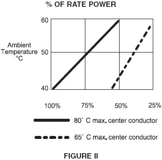
Figure II-Power rate
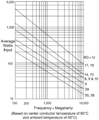
Mega Herz Figure III
Another very important consideration related not only to power but to attenuation is VSWR. VSWR is Voltage Standing Wave Ratio. This is the ratio of the voltage maximum to voltage minimum existing on a coaxial cable. It occurs when there is discontinuity or mismatch to the cable (e.g., do not use 50 ohms load for 75 ohms system). This variation from the theoretically ideal causes a reflection of the incident wave. The reflected wave and incident wave produce a standing wave. For maximum energy transfer, the importance of this relationship becomes most apparent.
In many systems, a VSWR of 1.3 maximum can be tolerated but the lower the VSWR, the better becomes the finished system. Figure IV shows what happens when VSWR goes above 1.0. When VSWR increases, attenuation increases. The difficulty in obtaining a low VSWR is readily seen when one realizes the actual VSWR of any component is apt to be better than the overall VSWR measured. If we could get ideally perfectly matched connectors and also make an ideally perfect termination, we could approach the ideal VSWR (assuming ideal cabling).
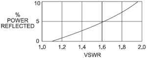
Figure IV
In addition to the RG types of coaxial cables, a complete list of which is shown on the pages which follow in this Technical Handbook and Catalog, there have been introduced many other types of RF transmission lines. One of the most popular commercial types is a group using foamed or cellular type dielectric. These type cables generally follow the characteristics of RG cables in the numbers 8, 11, 58, and 59. By using a unique method of manufacturing, air is introduced into the dielectric creating a dielectric very much like a sponge. This has a decided advantage over the solid dielectric in that a much better attenuation is achieved. However, the process of manufacturing is difficult to control and also there may be changes as the cable ages or is flexed, causing an increase in attenuation.
Another commercial group is the “air spaced” type. Various manufacturers market these transmission lines under various trade names. Essentially, they consist of the necessary “go” conductor around which is wound a helical vehicle to hold the “go” conductor in place. Generally the outer or “return” conductor is a solid sheath of copper or aluminum sometimes covered with polyethylene for mechanical protection and also for direct burial protection. The finished product shows a reliable, uniform, low loss cable. The popularity of these cables is gradually increasing due to their reliability and their rugged construction. They have advantages sought by the commercial users of transmission lines, the cable TV industry and also certain military system installations requiring exceptionally long life. Their advantages are: Little possibility of change in electrical characteristics due to aging; reduced maintenance costs; and uniformity resulting in good VSWR over the entire frequency range.
RG cable manufacturing
the group of RG cables known as semi-solid dielectric cables, such as RG 62/U, RG 71/U, and RG 63/U, have one thing in common. They have a center conductor around which a polyethylene thread is helically wound and then over the thread, a polyethylene dielectric is extruded. In this respect all of the various groups are the same in basic design and construction up to the braid stage. We will discuss the above group since they are the more difficult to manufacture.
The “go” conductor used in the RG 62/U and RG 71/U groups is a copper-clad steel core wire, “Copperweld ®”. Copperweld® is made by a carefully controlled process wherein a thick copper covering is inseparably welded to a high strength steel core. In the case of RG 62/U and RG 71/U, the “go” conductor is 22 gauge with a nominal diameter of 0.0253″. Since high frequency currents travel mainly in the outer skin of an electrical conductor, the Copperweld® is used in these cables to provide the unique combination of high strength along with electrical conductance.
The originality of such a design exhibits the complexity of choice involved in selecting conductors for coaxial cable. Table 1 lists some major characteristics of various conductors in popular use today. Use and application of the finished cable must not be slighted in the final design criteria. The manufacturing process of RG 62/U or RG 71/U groups requires several operations. In the first operation, the polyethylene thread is spiraled around the conductor.
In the second operation, the dielectric is extruded over the conductor and spiraled thread. In this operation, there is a possibility of breakage of the conductor due to the fact that the spiraled thread is not always even in diameter and it may cause a jam in the extruder tip. This jam will cause a momentary stoppage and the resulting jerk may cause breakage. The extruded insulation is “spark tested” as part of the extrusion operation to make sure there are no voids or holes in the dielectric. (The inner conductor is at ground potential.) Any pinhole in the dielectric will result in a spark failure, which is recorded as to location and reel number so that it may be cut out before passing through remaining operations.
The next operation is braiding. The extruded core is braided with one or two shields as required by the specification. During this operation, and all remaining operations, the cable is under constant tension. Following the braiding operation, the cable receives an extruded jacket. Again, the cable passes through a chain electrode at high potential to detect any jacket deficiencies. (The braid in this case is at ground potential.)
When the dielectric of polyethylene coaxial cable (whether it is solid or semi-solid) is extruded, strains develop in the material. In theory, these strains are reduced by the use of hot water in the cooling trough. As the dielectric is run through the cooling trough, it runs through very hot water to cool water in graduated steps; therefore, most of the strain should have been relieved. The remaining operations all keep this first extrusion under tension, so that any strains which might have been retained from the extrusion operation have little opportunity to be relieved. When the cable is unreeled, this releases strains if any are present and there could be a conductor movement disproportionate to dielectric movement which might show up only in localized areas. To detect this possible trouble area, the “sweep test ” may be used.
As is seen from the preceding explanation, there are possible problems arising in the manufacture of coaxial cable. Some physical problems may lead to electronic problems. For these reasons, manufacturers are constantly improving process controls so that the finished cable will meet the highest standards.
The manufacture of coaxial cable is an exacting process and the very sophisticated application to which it is put, demands the highest quality.
Coaxial cable is probably the most versatile type of cable in existence today. Its development was one of the truly great milestones in the science of long- distance communication as well as transmission of highly complex signals within a relatively simple cable.t
If these are informative to you,please share with your friends
 Ready to Transform Your Theoretical Cable Schematic into a Production-Ready Master Spool?
Partner Direct with an Agile, ISO 13485 Certified Medical OEM Factory.
Don’t let engineering calculations bottleneck your project timeline. Fill out the specification layout form below, upload your active connection draft or core requirements, and request a Free Factory Engineering Evaluation and custom sample spools from Shen Zhen Yong Qiang Fu Industry Co.,Ltd. today!